So, it has been a few weeks since I installed the preamp and the tablet. I ran into some issues with the wireless connection on the tablet and had to go with a different Tablet but it is working fine now.
Of course, the preamp itself worked flawlessly!
Anyway, enough about this for now. I have flown the coup for a few weeks but will continue to research this and possibly make a small product out of it.
Until next time on this side, I am over and out on the flip side, heading for My Southern Exposure!You kids stay safe now......
Thursday, May 22, 2014
Thursday, May 8, 2014
Pelham Hall 4 - Packaging Hell – The finished Product
So, after trying several “around the house” boxes with
little success (too big; too small; not enough access) I broke down and walked
to Radio Shack for one of their stock boxes:
Thinking that this
enclosure would allow me to position the input jack flush against one of the
sides - remember, the input jack is on
one edge of the board - it would make the packaging sweet!
Well, once I got
the box home and opened it up, I figured out that this could not happen. The
four lid mounting pillars extended all the way to the bottom of the enclosure,
making sure that board could not be placed flush with one of the short sides. Since the
board standoffs were on its edges, I would have had to remove those, cut the
board down, and figure out another place for mounting that end of the board
(AARGGGHHH!!!).
Since I had no
desire to re-architect the board mounting, I knew my only option was to drill a
really large hole in the side to accommodate the input jack. Bummer.
Anyway, after
playing around with different board mount ideas, I settled on the plan of
mounting the board, the power connector, and the RCA jacks, on the lid of the
box. A quick (yeah right) cardboard template of the inside of the Box plastic
top allowed me to locate the board standoff locations (as close to one end of
the box as possible), and a reasonable layout for the power and output
connectors. Punching and drilling the holes in the plastic to was a bit of a
challenge, without the proper clamps and supports but I got it done. I miss not having a model shop!!!!
Below is the
enclosure plastic top with the board mounted and connectors mounted and wired
up.

This side view gives a better indication of where things are.

And a view of the connectors.

Next was to locate
and drill the GIGANTOR hole in the side of the box. Fortunately, I had one big
drill to make that hole, and even thought it looks a little jack-Leg, functionally,
it works!
The final Preamp,
fully wired up from the Tablet to my old Stereo. Note the input connector (white cable on the left) goes almost all the way into the box (need to fix that in the version that will be put on Amazon and eBay!!!).


I have left the
Preamp plugged in for several days to make sure it is solid and I have turned on my
Stereo periodically to ensure music was still coming through. Next is the acid
test in place in Westchester.
Until soon…….
Tuesday, May 6, 2014
Pelham Hall 003 - BACK TO THE BENCH
Last week was a lost weekend since I was in training all
week and was catching up on work in the evenings. Come the weekend, I did
manage to get more done.
After stopping at Radio Shack and picking up a small proto
board, I got busy with planning and building stage 1 (Left Channel??).
Fortunately, I had held on to my construction tools over the years:
- Soldering Station
- OK Brand Wire Wrap (WW) tool
- OK WW unwrap tool
- Various WW wire spools
- BOURNS brand trimmer adjustment tool
- WW IC sockets and component headers
These became invaluable as I planned the build (see the
picture later…). I figured I would get back to this type of work at some point,
even if it was for hobby.
First, I needed a 3.5mm jack to accept the Table headphone
output. This was something I decided to buy from a hobby shop (Jameco). Along
with those, I ordered some additional LM741 IC’s, an assortment of resistors
and capacitors to ensure I had enough parts to tweak my design.
I forgot that
planning is everything
There were some challenges getting the components located in
a reasonable layout to accommodate everything on this small board. After
locating the headphone jack, I salvaged a power connector from another device
(old DSL modem) and mounted it next to the jack. The mounting was bugging so I
tried to super glue it to the board (bad idea!). Anyway, in the end, I pulled
it off and went with a 2 pin connector. Once this was in place, I realized this
arrangement would be perfect for the Left/Right output.
To the bench!!
Thinking about where to get the 2 pin connectors for this, I
realized that I have a few old PC chassis around that used these two pin
connectors to connect to the front panel LED’s and switches, so off came the
case of one (I should have thrown this out years ago!!) and the 2 pin cables
were snapped and interfaced (two for Left/Right to RCA plugs, one for the now
removed power connector).
The first stage was built and tested, with some component
values being adjusted to provide good dynamic range and variable gain.
Actually, in the end, the gain adjust is anywhere from 1 to 80 via a 100K ohm,
10-turn trimmer. This allows for the tablet volume to be set at about 50% and 4
turns of the trimmer to get a decent range.
The first stage was completed. Notice that the power connector is on the board at this stage.

Once this was mostly tested, the second stage was
built and tested. Below is a picture of the entire setup with the Right/Left RCA Jacks near the bottom right. Note that the power connector is no longer on board...more packaging work.
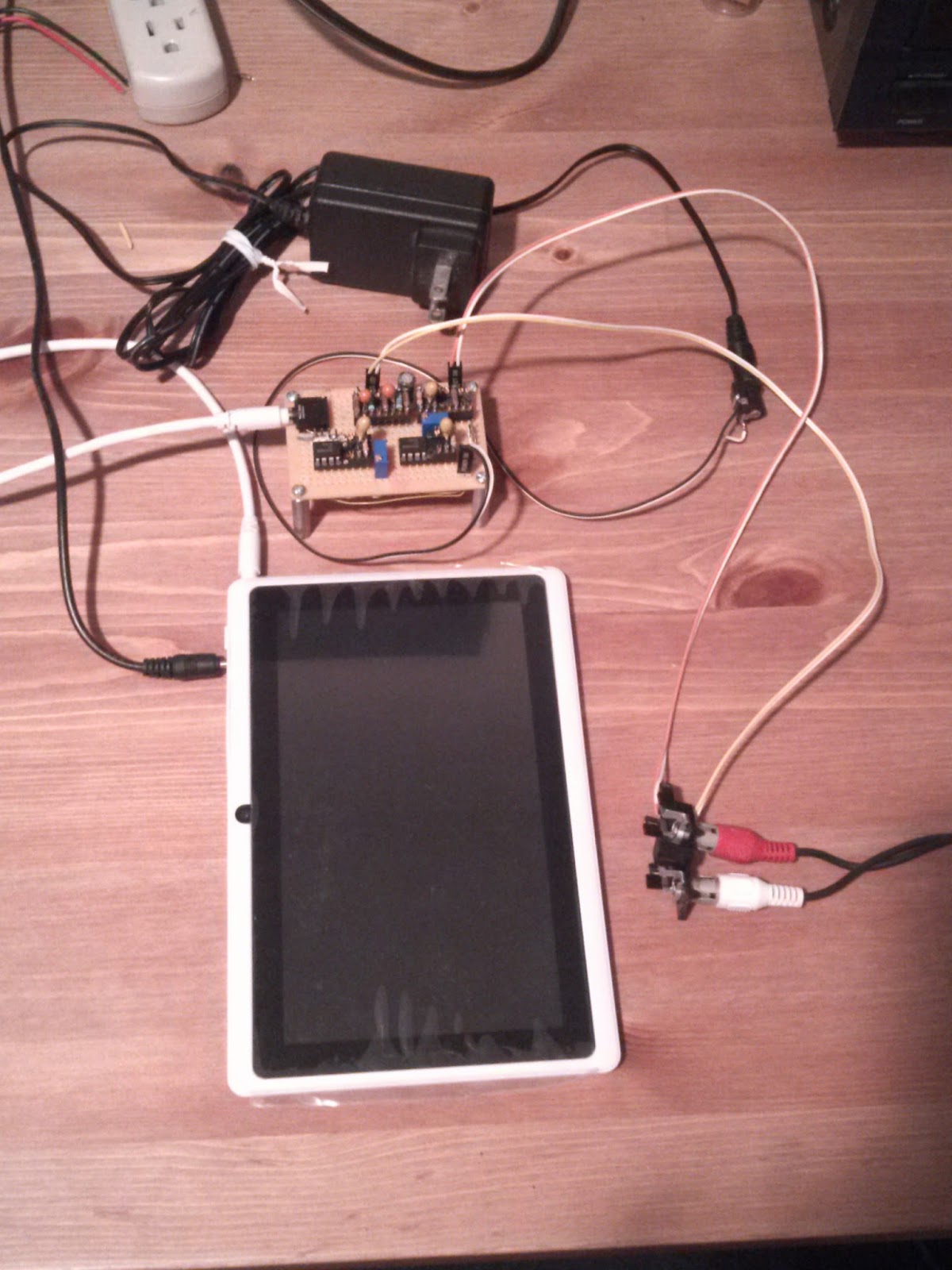
And here is a close up of the [mostly] completed preamp.Right/Left Line out cables are on top, with the power connector bottom right, and Headphone Jack in on the left (white cable).

Packaging
I have been thinking about packaging for the better part of
two weeks and after some false starts with “round-the-house” boxes, I am still
searching for the best fit. More when I figure that out.
Subscribe to:
Comments (Atom)