So the the signal dropped from time to time and often did not work at all, to the point that my mom stopped using it.
I knew that the use of that old "B" router was a bad plan. I headed north to first pick up a brand new Linksys "N" router (modern technology) from Best Buy and brought the small 7" tablet that worked flawlessly during MY SOUTHERN EXPOSURE.
Removed the old router, inserted and configured the new router (turning off the 'guest' wireless) and setting up the 7" tablet to connect to it.
Now, it is working as designed. My mom listens to the Jazz station almost everyday and she no longer has to go into the back room and turn on the computer to hear the station.
Of course, throughout the troubleshooting period, the preamp functioned without a hitch.
Still thinking about a product idea...
For now, until then, and maybe beyond, keep it within bounds and keep reaching for what you aspire to!
Wednesday, July 30, 2014
Thursday, May 22, 2014
Post Haste
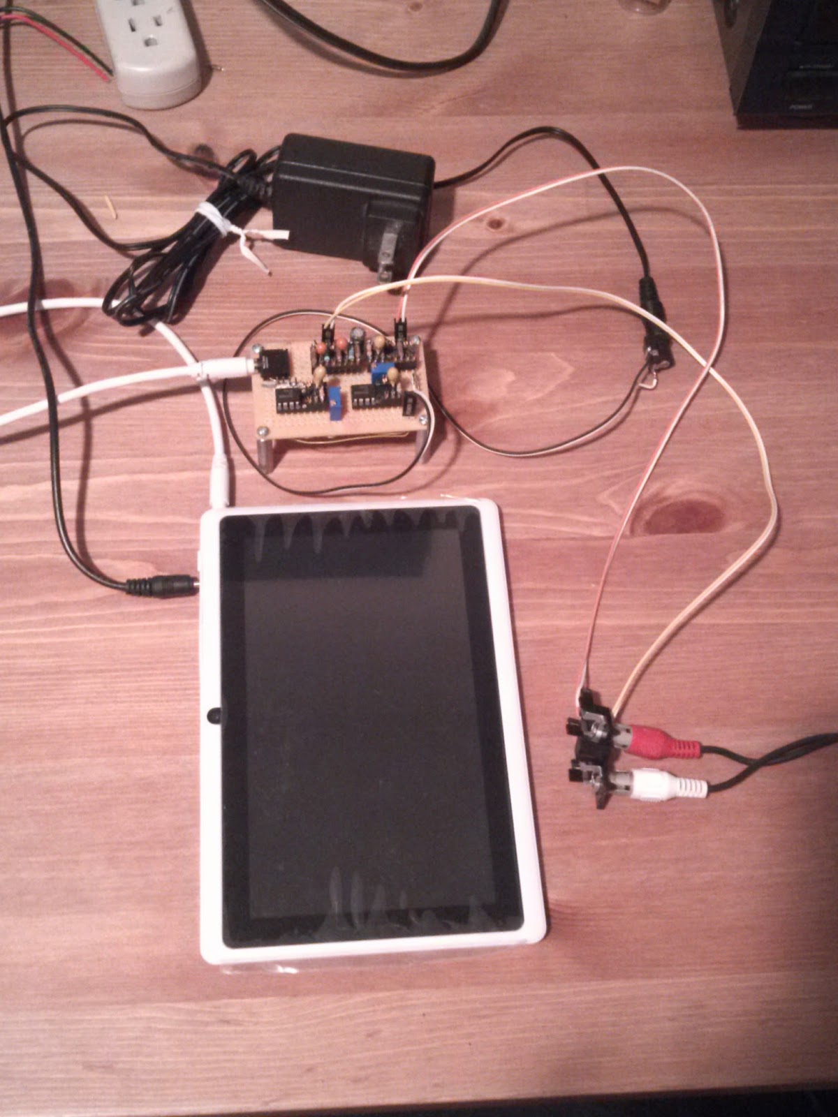
So, it has been a few weeks since I installed the preamp and the tablet. I ran into some issues with the wireless connection on the tablet and had to go with a different Tablet but it is working fine now.
Of course, the preamp itself worked flawlessly!
Anyway, enough about this for now. I have flown the coup for a few weeks but will continue to research this and possibly make a small product out of it.
Until next time on this side, I am over and out on the flip side, heading for My Southern Exposure!You kids stay safe now......
Thursday, May 8, 2014
Pelham Hall 4 - Packaging Hell – The finished Product
So, after trying several “around the house” boxes with
little success (too big; too small; not enough access) I broke down and walked
to Radio Shack for one of their stock boxes:
Thinking that this
enclosure would allow me to position the input jack flush against one of the
sides - remember, the input jack is on
one edge of the board - it would make the packaging sweet!
Well, once I got
the box home and opened it up, I figured out that this could not happen. The
four lid mounting pillars extended all the way to the bottom of the enclosure,
making sure that board could not be placed flush with one of the short sides. Since the
board standoffs were on its edges, I would have had to remove those, cut the
board down, and figure out another place for mounting that end of the board
(AARGGGHHH!!!).
Since I had no
desire to re-architect the board mounting, I knew my only option was to drill a
really large hole in the side to accommodate the input jack. Bummer.
Anyway, after
playing around with different board mount ideas, I settled on the plan of
mounting the board, the power connector, and the RCA jacks, on the lid of the
box. A quick (yeah right) cardboard template of the inside of the Box plastic
top allowed me to locate the board standoff locations (as close to one end of
the box as possible), and a reasonable layout for the power and output
connectors. Punching and drilling the holes in the plastic to was a bit of a
challenge, without the proper clamps and supports but I got it done. I miss not having a model shop!!!!
Below is the
enclosure plastic top with the board mounted and connectors mounted and wired
up.

This side view gives a better indication of where things are.

And a view of the connectors.

Next was to locate
and drill the GIGANTOR hole in the side of the box. Fortunately, I had one big
drill to make that hole, and even thought it looks a little jack-Leg, functionally,
it works!
The final Preamp,
fully wired up from the Tablet to my old Stereo. Note the input connector (white cable on the left) goes almost all the way into the box (need to fix that in the version that will be put on Amazon and eBay!!!).


I have left the
Preamp plugged in for several days to make sure it is solid and I have turned on my
Stereo periodically to ensure music was still coming through. Next is the acid
test in place in Westchester.
Until soon…….
Tuesday, May 6, 2014
Pelham Hall 003 - BACK TO THE BENCH
Last week was a lost weekend since I was in training all
week and was catching up on work in the evenings. Come the weekend, I did
manage to get more done.
After stopping at Radio Shack and picking up a small proto
board, I got busy with planning and building stage 1 (Left Channel??).
Fortunately, I had held on to my construction tools over the years:
- Soldering Station
- OK Brand Wire Wrap (WW) tool
- OK WW unwrap tool
- Various WW wire spools
- BOURNS brand trimmer adjustment tool
- WW IC sockets and component headers
These became invaluable as I planned the build (see the
picture later…). I figured I would get back to this type of work at some point,
even if it was for hobby.
First, I needed a 3.5mm jack to accept the Table headphone
output. This was something I decided to buy from a hobby shop (Jameco). Along
with those, I ordered some additional LM741 IC’s, an assortment of resistors
and capacitors to ensure I had enough parts to tweak my design.
I forgot that
planning is everything
There were some challenges getting the components located in
a reasonable layout to accommodate everything on this small board. After
locating the headphone jack, I salvaged a power connector from another device
(old DSL modem) and mounted it next to the jack. The mounting was bugging so I
tried to super glue it to the board (bad idea!). Anyway, in the end, I pulled
it off and went with a 2 pin connector. Once this was in place, I realized this
arrangement would be perfect for the Left/Right output.
To the bench!!
Thinking about where to get the 2 pin connectors for this, I
realized that I have a few old PC chassis around that used these two pin
connectors to connect to the front panel LED’s and switches, so off came the
case of one (I should have thrown this out years ago!!) and the 2 pin cables
were snapped and interfaced (two for Left/Right to RCA plugs, one for the now
removed power connector).
The first stage was built and tested, with some component
values being adjusted to provide good dynamic range and variable gain.
Actually, in the end, the gain adjust is anywhere from 1 to 80 via a 100K ohm,
10-turn trimmer. This allows for the tablet volume to be set at about 50% and 4
turns of the trimmer to get a decent range.
The first stage was completed. Notice that the power connector is on the board at this stage.

Once this was mostly tested, the second stage was
built and tested. Below is a picture of the entire setup with the Right/Left RCA Jacks near the bottom right. Note that the power connector is no longer on board...more packaging work.
And here is a close up of the [mostly] completed preamp.Right/Left Line out cables are on top, with the power connector bottom right, and Headphone Jack in on the left (white cable).

Packaging
I have been thinking about packaging for the better part of
two weeks and after some false starts with “round-the-house” boxes, I am still
searching for the best fit. More when I figure that out.
Saturday, April 26, 2014
More from Pelham Hall - Tablet Preamp Project
I am on call this weekend (covering for a colleague) so I am not going anywhere.
I was going to take a trip to Radio Shack to get the RCA Jack, cable, etc. to make a interface cable to the receiver when I realized that I have those in various places around the shack. So off I went to pull out, hack up, and wire in one side of a stereo RCA cable (note that I am working on one channel right now).
I pulled out my old DENON Stereo Receiver and one of the MINI ADVENT Stereo speakers. Dusting off was the first order of business but they wired up quickly and I had the MP3 preamp driving the CD Line input of the stereo to the single speaker. Next was to try my phone, and then finally the Tablet.
Below is a picture of the set up with the MP3 player and the Receiver. This set up also has the preamp powered by a 12VDC Brick, with the ATX power source removed.

After adjusting some levels and listening to the output of the receiver, I think I will alter the design slightly to give myself more gain (just feeback resistor values). The design already has a variable resistor such I can set the level when in place in the living room.
Waiting for my parts order to come in......Just about ready for figure out final design, connectors, packaging, etc.
I am on call this weekend (covering for a colleague) so I am not going anywhere.
I was going to take a trip to Radio Shack to get the RCA Jack, cable, etc. to make a interface cable to the receiver when I realized that I have those in various places around the shack. So off I went to pull out, hack up, and wire in one side of a stereo RCA cable (note that I am working on one channel right now).
I pulled out my old DENON Stereo Receiver and one of the MINI ADVENT Stereo speakers. Dusting off was the first order of business but they wired up quickly and I had the MP3 preamp driving the CD Line input of the stereo to the single speaker. Next was to try my phone, and then finally the Tablet.
Below is a picture of the set up with the MP3 player and the Receiver. This set up also has the preamp powered by a 12VDC Brick, with the ATX power source removed.
After adjusting some levels and listening to the output of the receiver, I think I will alter the design slightly to give myself more gain (just feeback resistor values). The design already has a variable resistor such I can set the level when in place in the living room.
Waiting for my parts order to come in......Just about ready for figure out final design, connectors, packaging, etc.
PELHAM HALL
I am designing a small interface between a Tablet headphone
Jack and the AUX Line-in RCA plug on a Stereo Receiver. This is to facilitate
my Mom listening to the Newark Jazz station in her living room via the
internet. Her apartment in New Rochelle faces northeast so she cannot receive
over the air signals from NJ.
I first had to install a wireless Router in her spare
bedroom where her Cable Modem and Computer reside. Next, I bought a $50 Android
Tablet that can run the WBGO App. The tablet was connected to the WiFi from the
Router, the app was loaded everything worked, except for the distance. As I got
closer to the Living room Stereo, the Wifi signal faded and the app stopped
playing. I will tackle the distance problem later. This was just a
Proof-of-Concept that the connection would function and her computer still
reached the internet.
Interface Planning
The next challenge is to convert the Tablet headphone jack
signal into something that can plug into the AUX input (Line Level) on her
Stereo.
·
- Took an old Stereo unit, gutted it, and placed a ATX PC Power Supply in it (on the left) to provide +/-5VDC, +/-12VDC, and +3.3VDC for the prototyping
- Pulled out my old MP3 player as an audio source
- Re-used the Tuner from that Stereo unit to access the headphone jack of the MP3 Player (to the right of the player)
- Built a single stage, 4x gain, audio preamp (Breadboard)

4/21/14
After completing my old stereo unit retrofit to a
multi-voltage power supply, I turned my attention to the components I would
need to set up a test bed:
- Stereo audio source with 3.5mm Headphone jack output – OLD MP3 Player
- Breadboard for prototyping – In House Proto Board
- 3.5mm plug cable to the termination point – Sandbox Component
- 3 Pin Termination for the Left/Right/Ground from the 3.5 mm – AM/FM Tuner from the Stereo Unit
- 3 Pin wiring from the termination to the breadboard – In House wiring
- +12VDC wires from the ATX source to the breadboard – In House wiring
- Oscilloscope to measure the signals – In House
After assembling these components and breaking out the old
trusty Soldering station, I got everything wired up and tested. The MP3 Player
had a number of full albums on it, which is working out fine for having varying
audio levels.
I Googled looking for some small Op Amp circuits and chose a few that
looked useable. Since my plan is not to have to use a dual supply, the amp
would need an offset such that I could use the +12VDC from my supply. The Proto
Board is already equipped with a +5VDC regulator, so I began at that step down,
assuming I would need to go to 12V eventually.
4/25/14
With the base amp set up working at about 2x gain, I started
to map out what the final amp would look like if I had all the correct
component values. Obviously, using a noisy switching Power Supply from my ATX
source is not going to show me reasonable noise levels, but I know the final
solution would contain a small brick power source that would be sufficiently
quiet for this purpose.
I figured I could get by with a single inverting Op Amp stage with a variable gain of 4. For testing, a LM741CN would do and I had 5 pieces in stock. Jameco had a number of parts that would be helpful during this design phase so I went ahead and ordered some parts:
Number Item Description
26403 TRANSISTOR,MPF102,JFET,TO-92
2131039 RESISTOR,
610 PACK E12-SERIES
853599 SEALED,CERMET,3/8IN,25TURNS
2168131 @JACK,AUDIO,STEREO,3.5MM,BLACK
2200954 PLUG,AUDIO,STEREO,3.5MM,MALE
24539 IC,LM741CN,DIP-8
Testing Dynamic Range
While the initial design seemed to be reasonably dynamic, I
knew I would need a stable sine wave source of multiple frequencies to really see
if there were any flaws in my design. I wanted to make sure my choice of
components would accurately reproduce the standard audio frequency range
without distortion or noise.
I had used a piece of Freeware in the past called “Audacity”
to record sounds and save WAV files. From memory, the app could also generate
sine wave tones. After installing the code and getting it to put out single
frequency tones, I searched around for a way to generate a sweep. Apparently,
Audacity can import script files (called Plug-ins) written in xLisp and a
language called Nyquist to control the sweep. The first thing found was this
code, called “Frequency Sweep”, written in Nyquist:
;nyquist plug-in
;version 1
;type generate
;name "Frequency Sweep..."
;action "Producing frequency
sweep..."
;info "by Adam Pope and Paul
Schimmel"
;control startf "Start Frequency
(Hz)" real "" 20 20 20000
;control endf "End Frequency
(Hz)" real "" 20000 20 20000
;control duration "Duration
(secs)" real "" 30 1 300
;control level "Level (dBFS)"
real " " 0 -40 0
;control type "Sweep scale [1=Linear,
2=Exponential]" int "" 2 1 2
(if (= type 2)
(scale-db level (fmosc 0 (pwev startf
duration endf))) (scale-db level (fmosc 0 (pwlv startf duration endf))) )
This code allowed me to set variables inside of Audacity for
start and end frequencies, duration of the run, etc.
However, the sweep runs once and stops so it looks like I might
have to learn some Nyquist programming in order to make audio a continuous
sweep. This will put me outside of my comfort zone but it is not like this is
the first time I have had to learn a language and write code in order to test
hardware I designed and built.
Learn to use your
tools
After referencing some Nyquist programming guides and
testing to loop commands, it was clear I would need to understand the current
code better in order to make this work.
4/26/14
After more playing with no success, I looked through the
menu items in Audacity and…low and behold…there was a menu item in the
“Transport” menu called “Loop Play”, which does exactly what I need. Now, I
have a continuous sweep tone generator that is fully configurable as to
Low->High Frequency range, duration of the sweep, and level. I plugged my
3.5mm extension cable into the audio out jack on my USB port replicator and
plugged the Termination plug into that.
I had to play with the duration and volume levels, but soon I had a nice 400hz-8000hz sweep into and out of my Preamp. On first blush, I had no serious bandwidth issues to deal with. Whatever noise is present is fairly low.
Next is to get a RCA cable and set up my old Stereo to see how it sounds.
Subscribe to:
Posts (Atom)